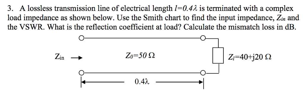
How much energy is supplied each second by that agent? Express your answer in terms of generic parameters and also as a specific energy for the given parameters. (d) The power at $x=0$ is supplied by the agent wiggling the left bar upward and downward. $ What is the value of this speed for the specified choices of these parameters? (b) If the positive $x$ -axis is oriented rightward and the steel bars are parallel to the $y$ -axis, the height of the sheet may be characterized as $z(x, y)=A \sin (k x-\omega t)$ What is the value of the wave number $k ?$ (c) Write down an expression with generic parameters for the rate of rightward energy transfer by the slice of sheet at a given value of $x$ at generic time $t$. (a) Use a twodimensional generalization of the discussion in Section 15.4 to derive an expression for the velocity with which the waves move along the sheet in terms of generic values of $W, L, F, M, f,$ and $A. The right side of the sheet moves upward and downward freely as these waves complete their traversal. That is, different frequency components of a signal travel at different speeds, and the phase velocity, vp, and group velocity, vg, are functions of frequency. This sends waves spanning the width of the sheet rippling from left to right. On a lossy line, phase velocity, group velocity, and attenuation constant are frequency dependent and so a lossy line is, in general, dispersive. Ifthe line ` has length L and is terminated by a load having an impedance ZR the values of which are specified in the table shown below (based on your last name), Determine (using Smith Chart): a) the input impedance, Zin(lossless) of the line (in rectangular form) if the losses are ignored, b) the actual input impedance Zin(lossy) of the lossy line (in rectangular form), and the actual reflection coefficient in(lossy), (in polar form) seen at the input (sending-end) of the lossy line Note To receive credit for each part of this problem, you MUST UTILIZE a Smith Chart in order to solve each of the impedance and refiection coefficient values and, when utilizing that Smith Chart, you MUST completely LABEL every point or value that you either plot on or read from the Smith Chart andor its accompanying scales:Ī rectangular neoprene sheet has width $W=1.00 \mathrm$. Where \$r\$ is your resistance, \$j\$ is your imaginary number \$\sqrt\$ and \$x\$ is your reactance which is your "resistance" of your capacitance or inductance, so to speak.Problem #7) Given lossy transmission line that has the following characteristics when supplied by 450 MHz source: Zo = 50 9, Y = 0.30 Nplm + j12.083 radlm. Remember that your formula for impedance is: If the impedance was only real and not complex, it would mean your transmission line would be purely resistive with no indication of induction or capacitance.

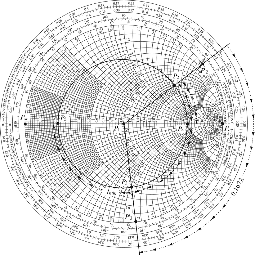
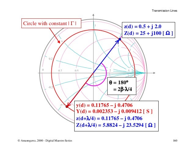
I'm not sure what you mean by "assuming the TL impedance is real". Otherwise if the reflection coefficient, \$\Gamma=-j\$, it would indicate a purely capacitive load. Henceforth, using the picture above, if the reflection coefficient, \$\Gamma=j\$, it would mean that the transmission has a purely inductive load. If you had to cut horizontal line across the middle of this circle in half, you would see that top half would be a more inductive load and the bottom half being a more capacitive load. real axis, you can basically determine real and imaginary components of the impedance. Wikipedia has a very good image of how the Smith Chart is organized (for impedance):


Forgive me for my knowledge of transmission lines and microwave circuits is very minuscule.


 0 kommentar(er)
